Which voltage lies between A and B in this question?
Option B, 2 V, is correct: this Zener diode and p-n junction NEET 2026 question asks for the voltage magnitude across the series resistor, not the diode. The source is NEET UG 2026, re-held on 2026-06-21, Code-50, Physics, Electronic Devices. “Medium difficulty” is the question bank’s classification, not an official exam rating.
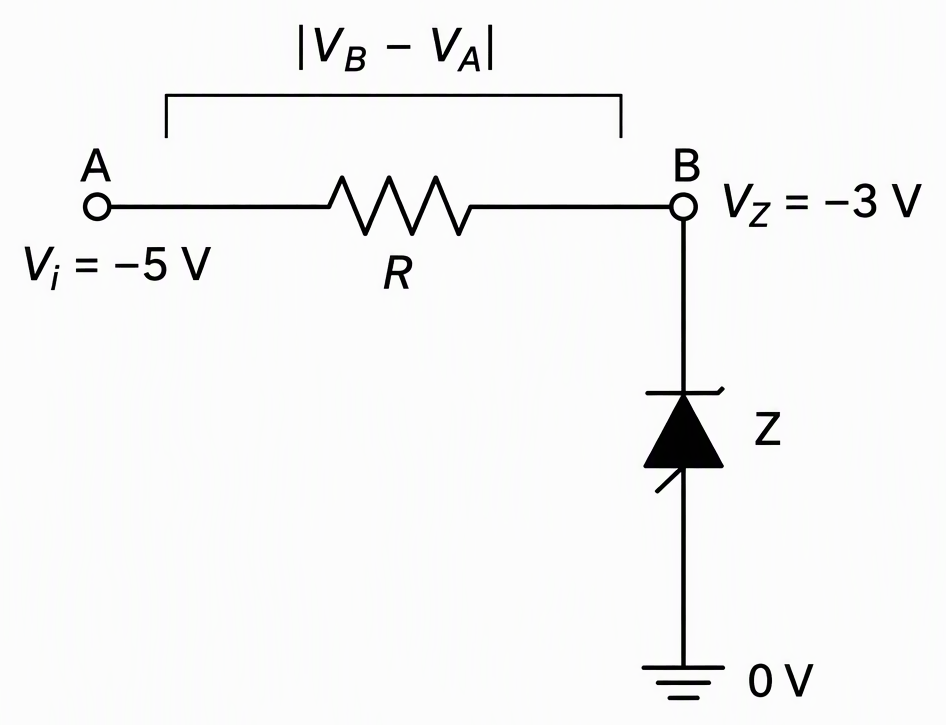
An ideal reverse-biased Zener has a signed breakdown voltage of −3 V and receives an input of −5 V. Find the magnitude of the potential difference between the two points spanning its series resistor.
The original diagram is not supplied here. The illustration reconstructs the standard series-resistor arrangement described in the official solution, with A as the input end and B as the resistor–Zener junction as an explicit drawing convention.
The supplied choices are:
How do you check whether the Zener is in reverse breakdown?
The ideal Zener operates in reverse breakdown because the reverse input magnitude exceeds its breakdown magnitude in this series-resistor circuit. Check this condition before assigning the clamped voltage.
The given signed values are:
Compare their magnitudes, not their signed numerical order:
The negative signs specify polarity relative to the reference. They do not mean that the input has insufficient reverse voltage to reach breakdown.
The diode therefore maintains a signed terminal voltage of −3 V. The remaining input voltage appears across the series resistor.
This clamping rule applies while the Zener is in breakdown and within operating limits. It does not apply to every possible reverse input.
How do you subtract the voltages without losing the minus sign?
Use the official method: signed resistor drop equals input voltage minus signed Zener voltage. Keep the signs through the subtraction, then take the requested magnitude. Taking absolute values too early hides the measurement direction.
Substitute both signed values, keeping brackets around the negative breakdown voltage:
Subtracting a negative becomes addition:
Now take the magnitude:
The reconstructed labels make the direction explicit:
Reversing the order reverses the sign:
Both orders have the same magnitude. The negative result in the official subtraction records the chosen direction, not a negative magnitude.
Check the voltage balance using the same convention:
No resistance value is required: the question asks for voltage, not current. Once breakdown fixes the junction potential, the two endpoint potentials determine the resistor voltage.
Answer: option B.
Why does 3 V answer a different question?
3 V is the voltage magnitude across the Zener, not across the resistor between A and B. Option A uses the correct breakdown magnitude at the wrong measurement points.
The faulty method is to recall the Zener’s 3 V breakdown magnitude and report it without locating A and B. Compare the actual measurements:
- Across the Zener: measure between B and the 0 V reference. The magnitude is 3 V.
- Across the series resistor: measure between A and B. The magnitude is 2 V.
A correct device property can still produce a wrong MCQ answer when applied to a different pair of terminals. Identify both endpoints of the requested voltage before selecting a device formula. Here, subtract the node potentials rather than quote the breakdown voltage.
What related Electronic Devices questions should you practise next?
Practise changing the measurement points, reversing the subtraction order and checking the device type. These are original practice questions linked to the solved PYQ, not additional verified NEET past-paper questions. Attempt each before reading its worked answer.
In the same circuit, what voltage magnitude is measured directly across the Zener?
The reading is 3 V, because the diode is operating in reverse breakdown. This measurement uses B and the 0 V reference, not the two ends of the resistor.
With A at −5 V and B at −3 V, what does each subtraction order give?
B minus A gives positive 2 V; A minus B gives negative 2 V. Substitute the signed potentials before simplifying.
Both have magnitude 2 V. Reversing the measurement order changes polarity, not the size of the potential difference.
Does reverse bias alone make an ordinary p–n junction diode a Zener regulator?
No. Below breakdown, an ordinary p–n junction diode carries only a small reverse current. A Zener is designed for controlled reverse-breakdown operation with current limiting.
The series resistor limits that current and takes the voltage left after the Zener’s clamped voltage is accounted for. A fixed diode voltage does not remove the need to control current.
Use this order on your next circuit question: identify the measured terminals, check breakdown, subtract signed voltages, then take the requested magnitude.
Next step: the past-paper archive on NEET JEEnius AI and search past NEET papers by year, subject or chapter, each with a worked solution (100 free searches a month).
Keep going with How to Study Reproductive Health NEET: NCERT Recall.
Frequently asked questions
Why is the answer 2 V and not 3 V in this Zener diode question?
The question asks for the voltage magnitude across the series resistor, not across the Zener. The signed resistor voltage is −5 − (−3) = −2 V, whose magnitude is 2 V. The 3 V value belongs to the Zener, so option B is correct.
How does a −5 V input cause breakdown in a −3 V Zener?
Compare the reverse-voltage magnitudes: 5 V exceeds the 3 V breakdown magnitude. The negative signs indicate polarity relative to the reference, not insufficient reverse voltage. In this ideal series-resistor circuit, the Zener therefore operates in reverse breakdown.
Do I need the resistance value to find the voltage across the resistor?
No resistance value is needed for this voltage calculation. Once ideal Zener breakdown fixes one resistor endpoint at −3 V and the input fixes the other at −5 V, their potential difference has magnitude 2 V. The resistance value would be needed to calculate the current.
Can an ordinary p-n junction diode work as a Zener regulator?
Reverse bias alone does not make an ordinary p-n junction diode a Zener regulator. Below breakdown, an ordinary diode carries only a small reverse current. A Zener is designed for controlled reverse-breakdown operation and requires current limiting, provided here by the series resistor.